
Introduction
Far beyond being a nuisance and safety annoyance in controlled areas, including airports, oil fields, and political areas, liquidation of drones is possible (Monte, 2021). Drones are not simple toys; drones have been used recently on an oil field in Saudi Arabia, in the United Arab Emirates, and in Syria (‘Drone strike deals a blow to Saudi energy ambitions’, 2019). On 14 May 2019, ten coordinated attacks using suicide drones caused fires at a central oil processing facility and nearby oil and gas fields in the Abqaiq processing facility. This attack led to around 50% of the Saudi daily petrol production being suspended. Saudi Arabia stopped oil production after the irregular attack on its oil-field station. On August 4, 2018, two suicide drones detonated explosives in Caracas, Venezuela, while President Maduro spoke to the Bolivarian National Guard. The Venezuelan government says the event was a targeted attempt to assassinate President Maduro (Vaz, 2018). Prisoners used a rogue drone to deliver drugs straight to a prisoner’s cell windows in an individual smuggling bid in Manchester in April 22, 2016, and similarly in Belgium in 2019. The drone costs around $145; they are capable of closing airports and sparking global turmoil. In the future, they could push a government closer and closer to an all-out war (Englund, 2019). The existing technology cannot control and neutralise autonomous pilot drones (Bertizzolo et al., 2020). The following technologies can be used to disable suicide drones:
- Anti-drone jammer system (333 MHz to 6.2 GHz);
- Anti-drone airborne net-guns;
- Counter-drone hand-held gun jammer;
- Anti-drone trained eagle & Anti-drone catch, class (Wajeeha, 2016);
- The counter-drone laser system.
The increasing number of attacks by modified and programmed drones shows the limitations of the existing technology for destroying errant drones in the Middle East (Archambault and Veilleux-Lepage, 2020). Day by day, the number of rogue drone attacks increases in the Yemeni and Libyan conflicts (Donnelly, Jacobs and Whitfield, 2020). Many governments purchase costly technology aimed at destroying illegal drones, but in reality, the above technology is not efficient enough (Mîndroiu and Mototolea, 2019). The following section looks at the danger of rogue drones in our public lives and the possibility of terrorist groups, drug dealers, and organised criminals using this technology (Plaw, Gurgel and Plascencia, 2020), as shown in Fig. 1.
The current technology has many drawbacks, as illustrated by the following examples (Cureton, 2020):
- The jammer device can cut off the radio-frequency links with drones, but it absolutely cannot neutralise autonomous pilot drones (Tedeschi, Oligeri and Di Pietro, 2020);
- Radar cannot detect low cross-section devices (Yaacoub et al., 2020);
- The jammer cannot stop drones working with a frequency link range higher than 6.2 GHz (Chamola et al., 2021);
- Recently, many criminals and terrorists have implanted anti-jammer systems inside the suicide drone, which means the radio frequency jammer cannot stop it (Colton, 2019);
- Full automation drone, it will be able to use all tools as autonomous learning systems for planning a flight;
- The radio communication between the drone and the operating stations is lost due to radio frequency interference; the enemy drone can continue its mission independently (Chaari and Al-Maadeed, 2021);
- High-energy laser cannon already tested against drones with promising results, but there are drawbacks in lousy weather (Archambault and Veilleux-Lepage, 2020). These include an energy requirement that is too high (3-5 kW or more) and reflective drone surfaces that can bounce the laser beam off the target, negating its ef-fectiveness and possibly putting ground personnel or other airborne platforms at risk (Chaari, 2020).
In conclusion, it appears there is no natural system to counter illegal drones, no radio-frequency jammer or any other solution (Shi et al., 2018). For this reason, High-Power Microwaves (HPM) may be a better option.
Raytheon claims that during tests at Oklahoma in 2013, the PHASERTM HPM system could upset and damage a group of drones at realistic engagement distances (Pina, 2017, p. 33). This type of development is by no means unique to the US; China invests more than $300 million per year to study and make this system. The HPM weapons will become a significant risk to drones in 2025. The HPM technique can be used to upset the electronics of suicide drones while negating collateral damage worries. This technology makes it possible to prevent potential adversaries from attack or compel them to stop a course of action. There are two configurations of the HPM technique; a continuous wave and a pulsed wave. A continuous wave delivers a constant stream of microwave energy over a wide area in disapproval operations against drones. A pulsed wave gives high power, short-duration pulses of microwave energy, and can provide precise drones (Moafa, 2020). Pulsed-wave weapons engage a specific target set with the intent to upset or degrade its electrical components. HPM energy (directed energy) for using the electromagnetic field strength energy to maximise the power distribution from the antenna generates a strength field to upset and damage electronic components. We will study this energy but all the testing phases and steps will take place indoors because we cannot test the system out of the lab without authorisation.
High Power Microwaves Background
Principles and Applications
HPM directed energy weapons utilise energy within the electromagnetic spectrum (EMS) to disrupt, damage, degrade, or destroy illegal drones. They can theoretically use it against all groups of drones. Anti-drone weapons use HPM as they are traditionally limited by energy and beam physics and this can be mitigated through material hardening. They have a low cost per shot, an in-depth magazine, rapid advancements in power, and there is physical difficulty and cost associated with hardening airborne electronics against them. This can damage drone electronics, depending on the weapon’s pulse, drone distance gap, and drone characteristics (Liu, Wang and Jun, 2020). The system’s efficiency depends on the power level, microwave frequency, pulse duration, and pulse repetition interval. This pulse creates an electromagnetic (EM) field bordering the drone, typically measured in watts per square centimetre (W/cm2). The field produces extra power, energy potential, or power within the drone, measured in joules (J). The aim is to induce a strong enough flow of electrons in the drone material to cause adverse effects. Field strength is reduced proportional to the inverse square of the target range (R) or ( ) , assuming a directional antenna as the pulse source. The wide variety of drones necessitates the inclusion of various electronic components that are susceptible to HPM radiation (Tatum, 2017). These include sensors, communications, avionics, and propulsion/power plant systems, all with unique properties and vulnerabilities. The AFRL (Air Force Research Laboratory) catego-rises adverse HPM effects on these electronics on a five-level scale;
- No effect;
- Interference;
- Disturbance;
- Upset (Field strength around 8 KV/m);
- Damage (Field strength around 17 KV/m).
Operational amplifiers, widely used in integrated circuits, are standard components vulnerable to upset, with a threshold of 9x10⁻¹⁰ J. Among standard features most susceptible to damage are Gallium arsenide metal-semiconductor field-effect transistors (GaAs MESFET), used in radar and sensor systems, with a damage threshold as low as 10-7 J, as shown in Table 1. Simultaneously, upset and damage effects to standard electronic component coupling are typically associated with field strengths of 8 kV/m (bitter) and 15 to 20 kV/M (crack). The AFRL considers a field of electrical potential of 200 V/m or more robust as a threat to sensitive electronics in general (Majcher et al., 2020). This field strength is readily attainable with current HPM systems at combat-relevant ranges (Gu et al., 2020).
Table 1
Electronic device burnout and upset thresholds (Burdon, 2017, p. 37).
The miniaturisation, mobility, power, and range of HPM systems operated by allies and adversaries are likely to increase over the next few years. Three specific electromagnetic sources, namely the High Altitude Electromagnetic Pulse (HEMP), UltraWide-Band (UWB), and HPM, are divided according to the delivery mechanism and operating frequency band of the pulse. We will study the concept of the HPM upsetting the electronics mounted in drones in the next section. When the system detects rogue drones, the high-power microwave systems produce a high magnetic field, effectively stopping errant and suicide drones. To upset the electronic parts of the drone, all its components and parts need to be understood, as shown in Fig 2.
Drone components
All drone parts and elements are vital for a smooth and safe flight. Getting the details of a drone will give users extra self-confidence while flying. We will also know swiftly and easily which part can be upset. The main elements of a drone, as shown in Fig 3, are:

System design
The HPM cannon uses electromagnetic radiation to quickly destroy the rogue drone’s internal electronics or burn its structure (fibre carbon). A conical horn antenna should be high performance and have high directivity to fabricate a prototype with greater efficiency to stop the enemy drone. We chose the best microwave generator to damage a drone at a distance of 10 metres in the test phase (indoor lab testing). The designed system mainly consists of four parts: power supply, magnetron, tuner, and conical horn radiator. The magnetron-based generator is selected to drive the pulse power generator at an operating frequency of 2.4 GHz. The conical horn radiator with a gain of 14.33 dB is designed using CST Microwave software and fabricated and tested. The performance tests of the designed system will be conducted in a laboratory environment and field trials. A block diagram of the microwave-based EMP system is shown in Fig 4.
Power supply The DC power supply provides enough voltage and current to power the magnetron. It includes a capacitor diode and a transformer (high voltage and filament). Compared with switching or pulsed power supplies, the advantages of DC power supplies are simplicity and low cost. The microwave power is generated from an air-cooled magnetron with a DC input of 0 to 2.5 kV to drive a pulse generator. The output of the magnetron connects to a waveguide isolator. This isolator protects the magnetron from reflected microwave energy and provides a matched load to the magnetron for effective microwave energy generation. For impedance matching to match the propagated wave in the cavity waveguide, the metal stub depth was adjusted at different guide lengths. This reduces reflected power and maximises the coupling power to the conical horn radiator. The source of the microwave’s short-duration pulses (m the magnetron) and the coupling with the horn antenna will be discussed in the next section.
Study and design of microwave transmitter
Microwave transmitter source
There are three main microwave sources:
In vacuum tubes, such as the best-known magnetron, the wave tube, and Klystron are all strong sources of microwave power that convert electrical energy into RF energy. We chose the magnetron-like microwave generator for this study because it is an effective and inexpensive device (Chaari, 2015). Typical electricity to RF conversion efficiencies are between 75% and 92%. The Klystron is more costly and not as efficient as a magnetron. Although solid-state FET (Field Effect Transistor) sources are straightforward, they still give low efficiencies compared to power microwave tubes. The output power variety of a magnetron, Pmagnetron, varies from 1 kW to about 1.2 kW. Higher power magnetrons used for industrial applications can generate up to 5.5 kW of output power, as shown in Fig 5. In our research and prototype, we will use the MAG2481 magnetron.
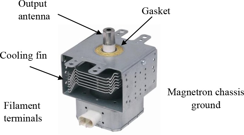
Magnetron operation
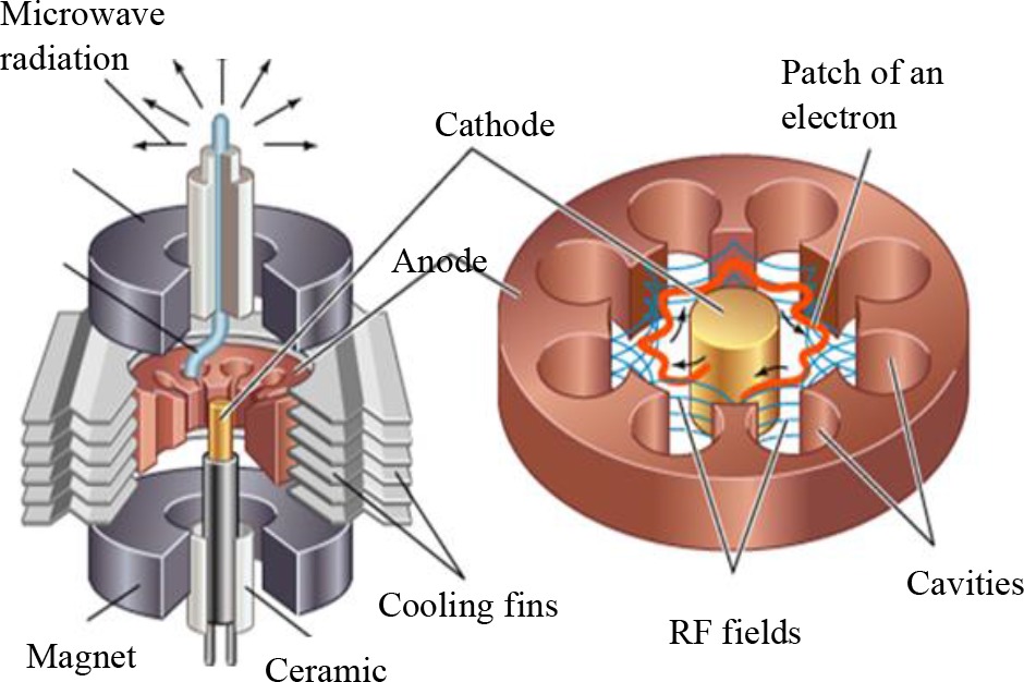
The anode of a microwave source is constructed into a cylindrical copper block. The cathode and filament are in the middle of the tube and are backed by the filament tap leads. The filament tap leads are significant and inelastic enough to maintain the cathode and filament structure fixed in location, as shown in Fig 6. The cathode is indirectly warmed and is made of a high-emission density material. The twenty cylindrical cavities around its girth are resonant cavities. Each resonant cavity works as an equivalent resonant circuit.
The free electrons will try to budge near the anode. However, the crossed magnetic and electric fields move in a circular path around the anode, as shown in Fig 7. As they travel in a circular path, they pass out of the anode’s cavities. Ceramic Magnet
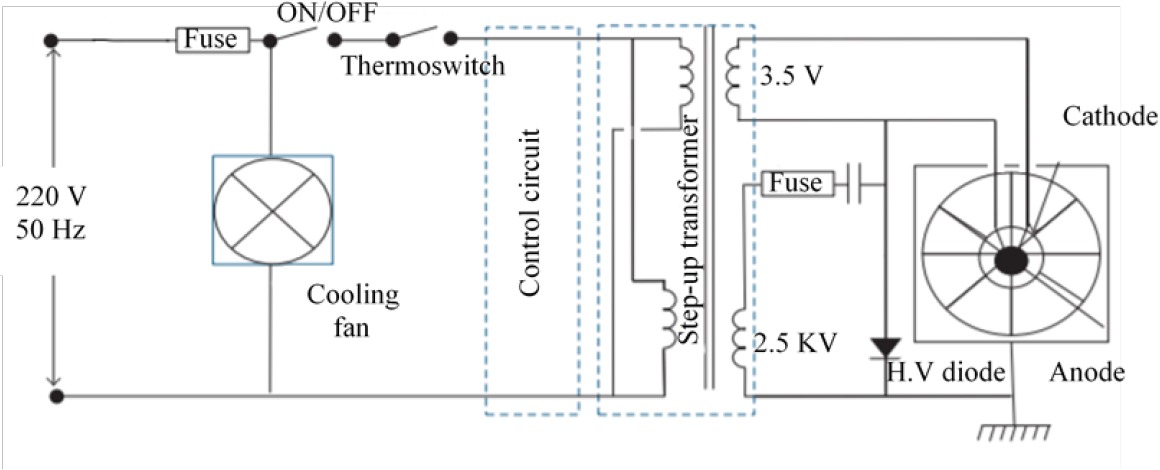
Magnetron power supply
The magnetron is a suitable device for the HPM because of its high efficiency and low cost. The magnetron can apply for high frequency and high power (Li, Huang and Zhao, 2020). This prototype requires high electrical power and a massive magnet. The alimentation circuit used for the magnetron consists of two-power systems, one low voltage around (3.5 V) and another high source voltage (2.5 KV) (Hubička et al., 2020), as shown in Fig 8.
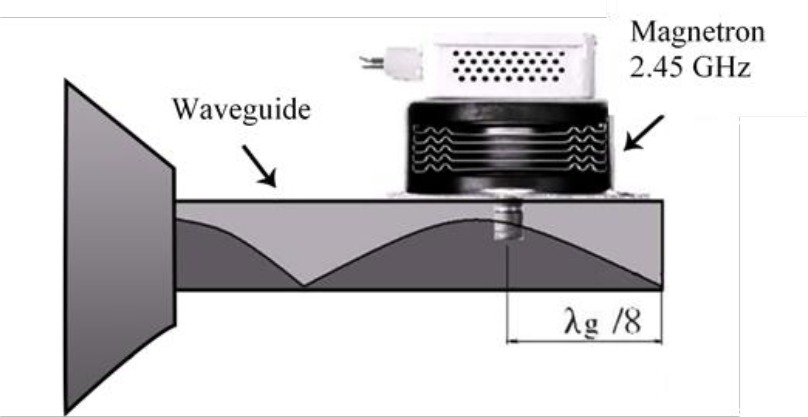
Magnetron coupling and tuning
The actual test can show the efficiency of the HPM short-duration pulses of microwave energy prototype changes according to the distance gap. This type of coupling uses a vertical radiator inserted into one end of the waveguide. Generally, the magnetron feed diameter is a quarter-wavelength of the operating frequency, as shown in Fig 9. The impedance adaptation between the conical horn antenna and the magnetron feed-pin source ensures the antenna’s maximum power distribution and generates a strength field to upset the drone electronics board.
Antenna Fabrication, Experimental Measurements, and Simulation Techniques
Most of the challenges are connected to coupling the pulse microwave generator with the horn antenna to get high efficiency and perfect impedance matching. The radiation power ratio is related to the beamwidth of the antenna (Teber, 2020).
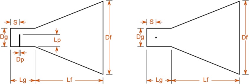
The dimensions of the conical horn antenna
The antenna size depends on the resonant frequency (f0), and the flare diameter (Df).
The gain of a horn antenna (Qi et al., 2020):
Where:
eA: Efficiency of the aperture (Between 0 and 1)
λ: wavelength (mm)
d: is the physical diameter of a conical horn aperture
The gain of the conical horn is optimum in the equation (Priya et al., 2020) (1):
For calculating the maximum phase deviation (S) (Pan, Cheng and Dong, 2020), we use equation (2).
Table 2 illustrates the calculated parameters of the horn antenna after simulations. We have created the conical horn antenna with the dimensions shown in Fig 10.
Table 2
Various parameters of horn antenna (fr= 2.45 GHz).
We affected many parameters such as directivity, reflection coefficient, radiation pattern 3D, current distribution, and the Smith plot.
The reflection coefficient of the antenna
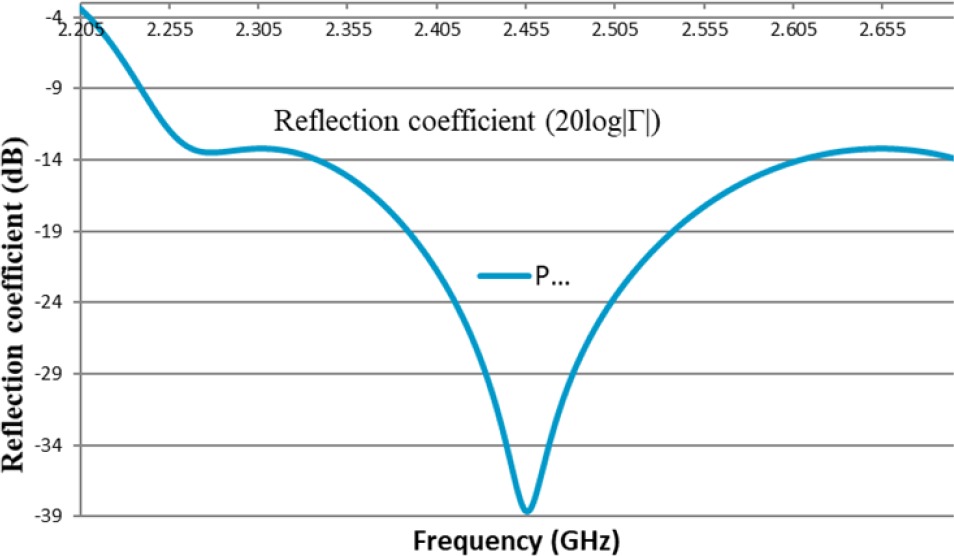
We obtain a reasonable return loss S11 = -22.611 dB at the operation frequency of 2.45 GHz, as shown in Fig 12. The antenna bandwidth is around 39 MHz and a standing wave ratio of 1.036 at 2.45 GHz.
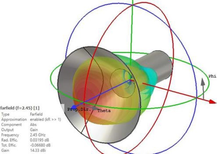
Radiation pattern 3D
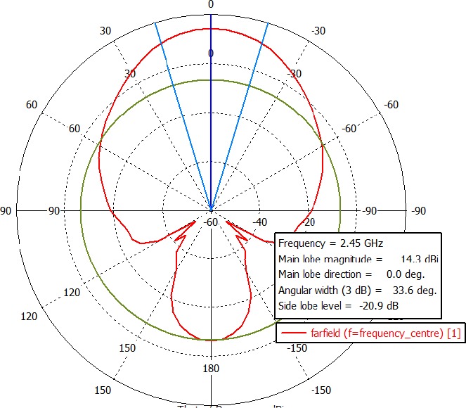
The antenna’s 3D radiation pattern shows that the radiation has a good directivity equal to 14.33 dB:
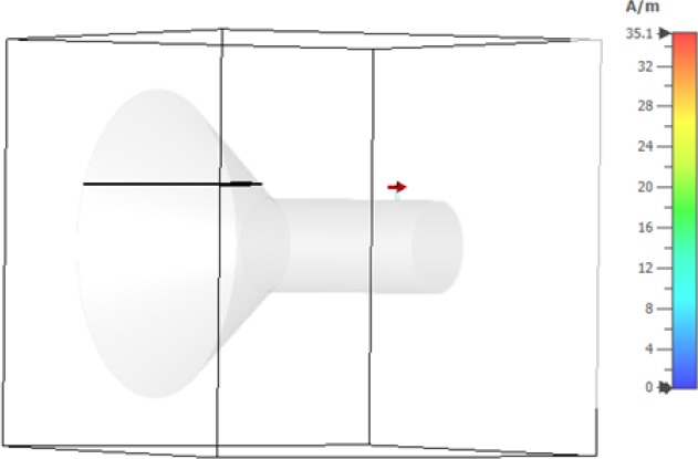
Current distribution
The simulation shows that the current distributions were different for different frequencies. We have high current distribution at 2.45 GHz, as shown in Fig 14.
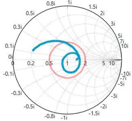
Smith plot
In the Smith chart, we can see that at frequency 2.5 GHz, the antenna is almost perfectly matched to the microwave source, with no imaginary part for the impedance, as shown in Fig 15.
After studying and analysing all the horn antenna parameters and the microwave generator, we will now explore prototyping and testing.
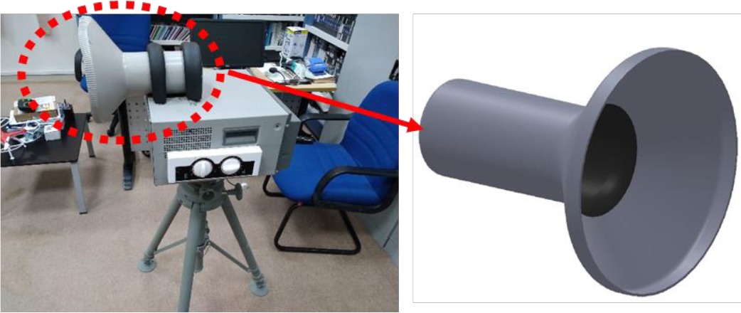
Prototype fabrication and testing Conical horn fabrication
This research provides a detailed description of the waveguide and the flared conical horn fabrication process. This section also describes all the equipment used, explains all the testing procedures and the locations chosen for testing radiation pattern measurements. This antenna was simulated in CST to match the high efficiency. After completing all the calculations and CST simulations on the conical horn antenna, the antenna was ready to be fabricated as the first experimental prototype. The horn antenna has been made from 1.5 mm thick aluminium plates, as shown in Fig 16.
Testing location
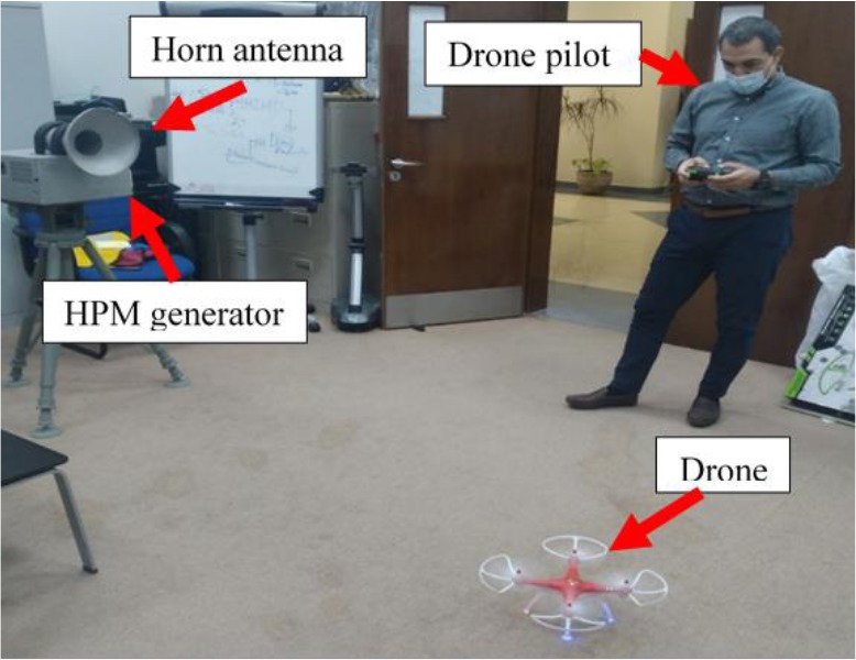
HPM directed energy cannon systems consist of a power source, magnetron, waveguide, antenna, and PWM control unit. They function by producing microwave radiation and directing that energy toward the drone place. This energy’s capability affects the electronic equipment of any drone. The conical horn radiator with a gain of 15 dB and 330 of 3-dB beamwidths is designed using CST software and made and tested using a Vector Network Analyser (VNA). We use the VNA TTR506A to measure the S11 of the fabricated horn antenna. After testing, we only have S11= -20.23 dB compared to -21.611 dB in theoretical simulation. The designed horn radiator is expected to have a low VSWR value of 1.075 at 2.45 GHz. The posterior horn’s cavity expects to be filled with a dielectric material to enhance the radiated electrical field’s intensity at the horn aperture to achieve those performances.
On the other hand, the proposed designed system’s performance tests will be conducted in a laboratory environment and laboratory trials. In this test, we keep the same drone types damaged with high microwave power, as shown in Fig 17. We change only the distance gap between the microwave source and the drone.
The lab does not have several obstructions, which eliminates most of the multipath interference, and the configuration also reduces ground reflections.
Results and discussion
This is an essential finding for understanding the efficiency of the HPM energy to stop the enemy drones. According to multiple factors and parameters, the power density delivered upset the drones’ electronics changes (Gt, Pt, Fr, …). Field strength lowering proportional to the inverse square of the target range (R) or ( ) , assuming a directional antenna as the pulse source is shown in Fig 18.
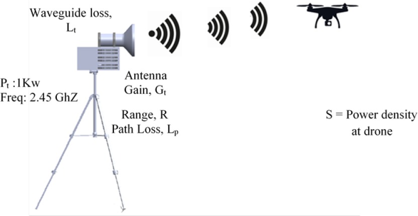
Effective Isotropic Radiated Power, EIRP (4)
Power density at the drone, S (5)
If we assume that path loss is its free space value:
Where: Transmitter power (Pt) = 1 KW
Estimated antenna gain (Gt) = 10 dBi
Estimated feeder waveguide losses (Lp) = 4 dB
Then the field strength at the target (S):
After the calculation and investigation of the field strength, it takes time for the drone’s electronics to be damaged because the field strength is very low at 10 metres.
The drone’s power density attack was reduced when the distance gap was high, as shown in Table 3. The transmitter power of 1kw is not enough for this type of application. The results are acceptable and show the benefit of using a conical horn antenna with a magnetron to quickly destroy the drone’s electronic components quickly.
Table 3
Range vs. power density at the target drone.
| Pt(W) | Range (m) | S (W/ | S (V/m) |
|---|---|---|---|
| 1000 | 10 | 31.69 | 109.3 |
| 20 | 7.92 | 54.64 | |
| 50 | 1.26 | 21.79 | |
| 100 | 0.31 | 10.81 | |
| 150 | 0.14 | 7.26 | |
| 200 | 0.079 | 5.45 |
Table 4 shows the experiment’s results and the time necessary to switch off the errant drone (damage its electronics components). The time taken to stop the drone is shown in Table 4, and when the gap between the ground station and drone is large, the UAV stopping time is longer.
Table 4
The time necessary to stop the drone and damage its electronic components.
| The gap distance between the HPM and the drone | The time needed to stop thedrone |
|---|---|
| 2 m | 2 min |
| 4 m | 6 min |
| 6 m | 13 min |
| 10 m | 17 min |
According to the experiment phase, the time needed to stop the rogue drone is related to the output microwave radiation and power, the firing duration, and the magnetron’s efficiency.
After the experiment test, we concluded that the drone switches off after some time because the pulsed microwave energy is not enough to produce field strength and can upset or damage electronic components. We figured that the HPM takes time to carbonise and stop illegal drones because the RF field strength is very low. The results demonstrated in this research match state-of-the-art methods. Here, we compared the results of the proposed method with those of the experimental methods. The HPM does not provide a perfect solution because it is affected by several external and physical limitations. In our test, seventeen minutes to stop an enemy drone is a long time; to reduce it should change the microwave source with high power and high frequency.
Conclusion
We proved that we could stop rogue drones with the HPM cannon in this research. The HPM cannon can destroy any unlicensed drone pilot by RF, GPS, and autonomously programmed drones. We tested the HPM cannon prototype utilising HPM energy pulses to cause a significant problem to enemy drones. The experiments show that HPM is a better solution with high efficiency that can destroy an autonomously programmed drone. The HPM technique is considered the best solution for reducing the risk of autonomous drones. After testing this prototype, we concluded that the technology has many drawbacks including:
Some drones use the dispersion of EMI through stable electronic architectures.
The Faraday cage can use shielding electronics from the HPM attack and radiation.
The disadvantage of these techniques comes from the threat of unintentionally disrupting telecommunications towers and electronic devices. The stop drone switches off immediately, falling uncontrolled to the ground.
All the simulated and real measurements show that the antenna performs exceptionally. We concluded that this technology is not enough to mitigate this danger. Regulation standards and roles in reducing the threat of rogue drones should be enforced. We advise regimes to apply strict laws on the use of drones. Buying normal drones from a shop requires at least $600, and to neutralise or destroy them, governments must spend more than $600,000.
In our testing phase, we proved that HPM technology is one of many solutions. Current challenges that need to be worked through before the HPM technique include extending their range and learning how the drone composition affects radiation absorption. In the future, we will use a high microwave source of 10 KW; the magnetron used is not enough for this kind of problem. The biggest challenge is whether the technology is ideal and satisfactory to cause discomfort to drones protected from electromagnetic impact (Faraday shield).