
Introduction
Previously, the combat soldier had a few items that required batteries, possibly a short-range VHF or UHF radio telecommunication, and a night vision scope (Brewster, 2020; Niesel, 2019). Every combatant had these and a requirement to power them. They included electronic sights, laser rangefinders, mini laptops, and a communications radio. What happens when a combatant’s wearable battery power level drops during combat? The response is evident in the number of military companies and laboratories working to solve this problem every year and the increasing number of scientific publications. Combat soldiers typically carry batteries for a 72-hour mission (Harper, 2015; Lafontaine, 2019; Miller, 2020). In Figure 1, we see they are concerned about reliable and timely resupply and ensuring their electronics and communications are available.

US soldiers not only carried weapons but also wearable batteries. For instance, on a 72-hour operation in Kabul and Baghdad, the average combat soldier had a sixteen-pound flak jacket, a sizeable weapon, and 40 pounds of gear, including batteries for communication, navigation, and powering monitoring devices (Collins, 2015). According to a British Ministry of Defence (MoD) study, every soldier carries around 12kg of batteries for a 36-hour patrol (Miller, 2020). According to a recent analysis by the Canadian Army, soldiers carry more than 51 AA batteries and CR123 batteries for a 24-hour guard (Thales, 2016). Battery placement has become one of the most critical considerations on today’s battlefields. The requirements for electrical power have grown-up exponentially over the last few years. Portable batteries have been a particular challenge for soldiers and special forces units. They must use all these devices continuously for three nights. The military is seeking longer battery charges, faster and more possibilities for recharging, extending the overall battery life, reducing the size and weight of batteries, and improving safety (Miller, 2020) . Achieving the promised capabilities offered by these technologies is directly linked to solving the power problem. The US army studies much research and works to reduce its combat soldiers’ enormous and literal burden. It held a competition in 2008 to find a 4-kilogram portable power supply that could provide 20 Watts for 96 hours (1.92 kilowatt-hours) of energy. Christopher Hurley and others developed fuel cells, smart grids, and environmental control units, harvesting wind and solar power and examining waste-to-energy and biofuels. He is working on more novel projects to develop a power source that converts commonly available sugars directly into electrical energy. He uses enzymes to convert sugar into energy, similar to how your body uses enzymes to convert food into energy (Sigler, 2011). Recently, the US army succeeded in implementing wireless recharge gadgets from 15 metres away (Beckhusen, 2012). In the plan, the branches’ research and development centres will contribute more than six million dollars to improve wireless energy transmission efficiency over greater distances, according to a US Army announcement. Chaari et al. produced a study of the impact of wireless power charging on the future of battlefields (Chaari and Al-Rahimi, 2021b).
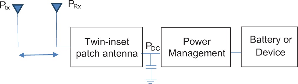
Using renewable energy sources such as solar chargers or wind power can reduce the load and weight of the batteries by providing energy. Wireless power transmission has become widely used in rescue applications because it can reduce the battery’s weight during firefighting operations (Chaari and Al-Rahimi, 2021a; Chaari and Rahimi, 2017; Sidhu et al., 2019). RF microwave energy would be sent to a small unit to wirelessly charge batteries in an electronic device (laser range finder, night vision goggles, infrared sight system, and radio system). Wireless charging solutions can reduce battery size, weight, endurance, fighting time and increase soldier strength. It consists of an RF transmitter part and a harvester circuit that uses high efficiency to harvest energy, as shown in Figure 2 and to provide electrical power to charge the wearable batteries on bulletproof vests using radiofrequency energy in the S-band (Ishibashi et al., 2019; Liu et al., 2020; Tran et al., 2017).
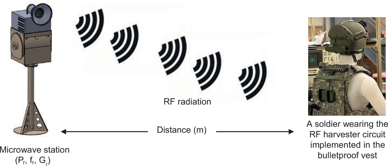
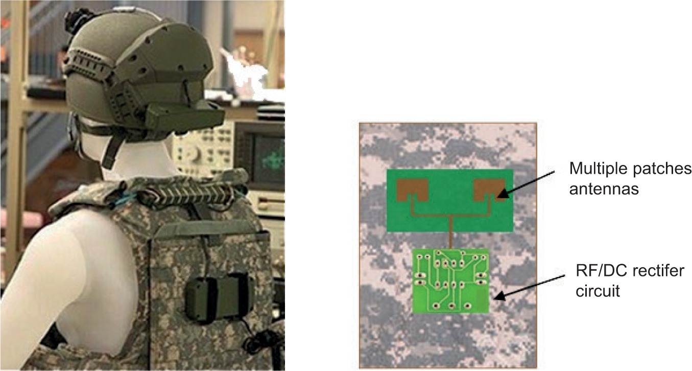
There are two main subsystems in the topology design. The first subsystem studied is the RF transmitter source coupling with a higher-performance pin-fed pyramidal horn antenna. The second subsystem uses an array patch antenna to harvest RF energy associated with a rectifier circuit at a higher efficiency (Pinto et al., 2021). This study looks at the possibility of energising many electronic devices by putting a soldier inside a bulletproof vest. It provides the most critical factor necessary for the soldier to perform his duties on the battlefield, namely, an approved electrical source from which to charge his battery for a 72-hour mission. This study examines the possibility of powering many electronic devices wirelessly using the harvester circuit on the bulletproof jacket, as illustrated in Figure 3. Scientists aim to reduce the weight of batteries for a 36-hour patrol to create a more intelligent battlefield. This study will examine two critical subsystems: an RF transmitter source and an RF-DC harvester. Estimating and calculating the amount of power loss in wireless power charging is necessary to determine the best antenna parameters.
Power Budget
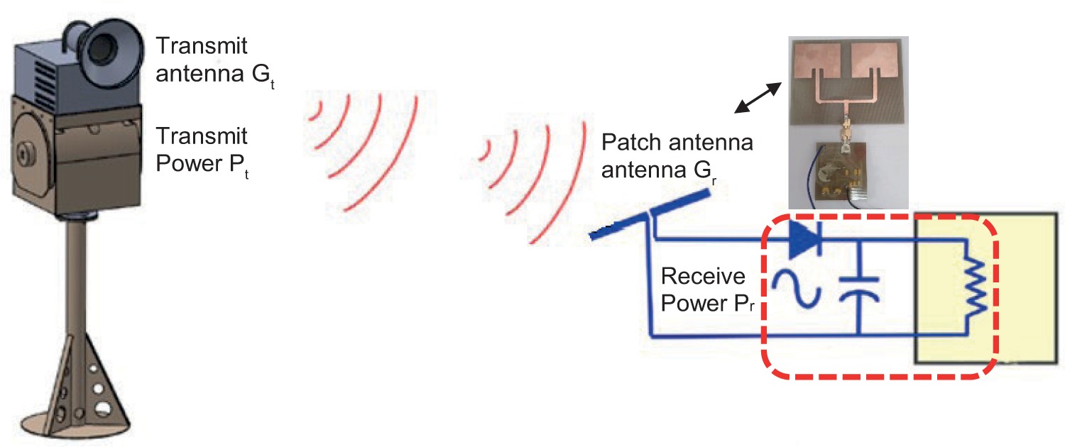
A transmitting antenna produces a power density Wt(θt,φt) in the direction (θt,φt). This power density attaches to the transmitting horn antenna Gain in the given direction G (θt,φt), on the power of the transmitter Pt fed to it, and on the distance (D) between the transmitting point and the observation point as
The required transmitter power is calculated using the effective receiving and transmitting antennas area, as shown in Figure 4.
To calculate the effective area of a patch antenna over a perfect ground plane, the following formula is used:
Where the wavelength
Where Gr is the Gain of the patch antenna, and λ is the wavelength at 2.45 GHz. From table 2, the Gain is G = 5.25 dBi. Using Equation (4), the effective area of the dipole antenna is 6.22 ×10⁻³ m2. The power density Wi transmitted by the conical horn antenna at distance R can be expressed as
Where:
Pt is the transmitted power,
Aet is the effective area of the conical transmitter horn antenna,
R is the distance between transmitting and receiving antennas.
For the conical horn antenna, the Gain (G) can be expressed as
The aperture efficiency (eA) can be expressed as
The effective area of the pin-fed horn antenna is the physical area (A) times the efficiency. The power (Pr) received by the dipole antenna can be expressed as:
Equation (9) shows the power required to transmit versus the distance between the transmitting and receiving antennas to obtain the maximum strength at the receiving point. Assume that distance R lies in the far-field of the conical horn antenna. This Equation describes the received power at close-in (reference) distances [W]
Close-in received power in dBm
Close-in received power in dBw
Received power calculated using reference power in dBm
Received power calculated using reference power in dBw
Equation (15) represents the path loss
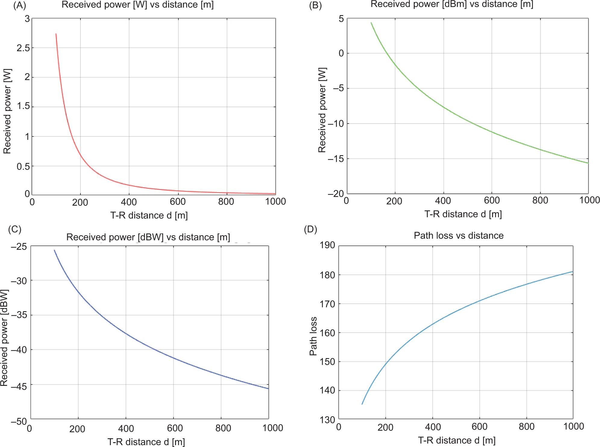
According to Equation (10), the reflection-free propagation where the far-field depends on distance as (1/r), while the power density falls off as (1/r2), as shown in Figure 5.
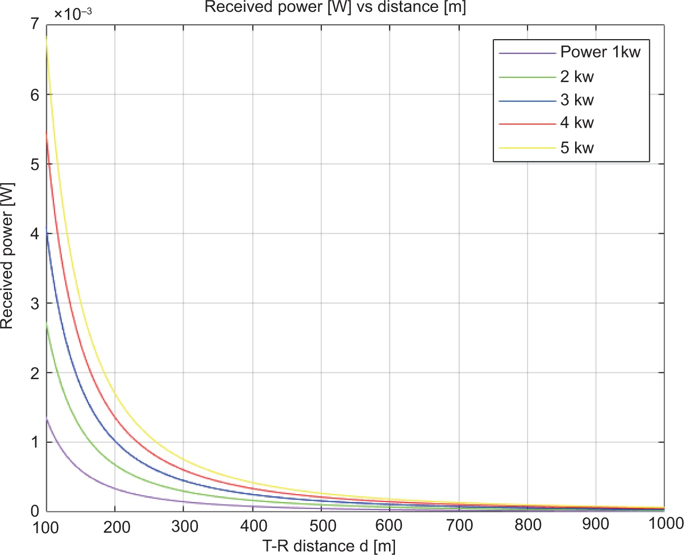
Figure 6 illustrates how the transmitter antenna should be positioned face-to-face with the receiver antenna to enhance energy harvesting from the RF transmitter source. The power density harvested depends on the direction of the receiving and transmitting antennas. We simulated the power received after the RF power transmission was set to 2 kW. Figure 6A illustrates the decrease in received power (W) as the gap distance increases, resulting in poor reception. Figures 6B and 6C show the received power (dBm, dBW) as the distance (m) function. There is no other effect other than the decrease in power due to distance and antenna parameters in the simulation. Antenna parameters are not included in the calculation of free-space path loss, as shown in Figure 6D.
RF microwave transmitter system
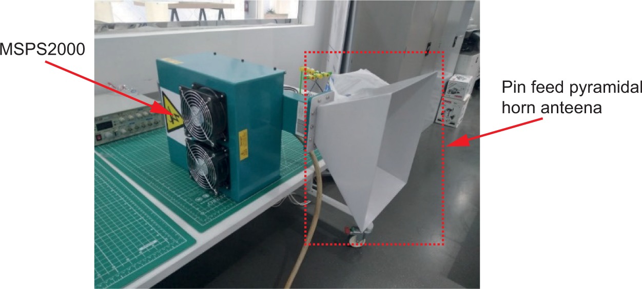
The microwave generator used in this study is an MSAPS (2kW Industrial Microwave Generator (MSPS2000)) (Park and Youii, 2020). As illustrated in Figure 7, these industrial microwave generators consist of a waveguide launcher, power supply, and magnetron in a compact enclosure, resulting in competitive, space-saving add-on generators. To increase the efficiency of RF transmission, we provided a water supply system for cooling.
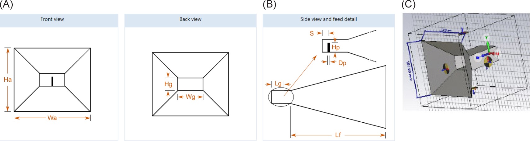
An antenna should be designed with high Gain and directivity to create a wireless charging device. The CST microwave simulator is used to simulate and optimise transmitter antennas, mainly for microwave radiation and power transmission. The radiation patterns of pin-fed horn antennas were taken into account when determining the maximum gain value, directivity, and area of operation of these antennas. Figure 8 contains a sketch of a pin-fed horn antenna with a linear flare.
Figure 8
The pin-feed pyramidal horn antenna sketches: (A) Front and back view, (B) Side view, (C) 3D view.
The Gain of a horn antenna is:
Dimensions of waveguides:
Wg = 0.8382 × λ = 98.05 mm (Waveguide width)
Hg = 0.3925 × λ = 124.91 mm (Waveguide length)
Where the aperture dimensions are:
Wa = 258.9 mm (Aperture width)
Ha = 187.0 mm (Aperture height)
The antenna metal thickness is:
Ts = 0.001 × wavelength centre = 0.001 × 124.913 mm = 0.1249 mm
Table 1 contains values derived from the CST microwave software. In the following sections, we discuss and analyse the results.
Table 1
Horn antenna parameters
All physical and electromagnetic properties of the pin-feed pyramidal horn antenna were investigated, including Reflection coefficient, Directivity, Smith Chart, and Radiation pattern 3D. Figure 9A demonstrates that we achieve a perfect return loss of -29.875 dB at 2.45 GHz. The antenna bandwidth is approximately 450 MHz (18.26%) at 2.45 GHz, and the Voltage Standing Wave Ratio (VSWR) is 1.07. Figure 9B shows the directivity gain at 2450 MHz is 12.71 dB. Input impedance is measured using the Smith chart.
Figure 9
Simulation of pin feed horn antennas: (A) Reflection coefficient of a horn antenna, (B) The directivity Gain of the transmitter, (C) smith chart, 3-D radiation pattern plots (D)
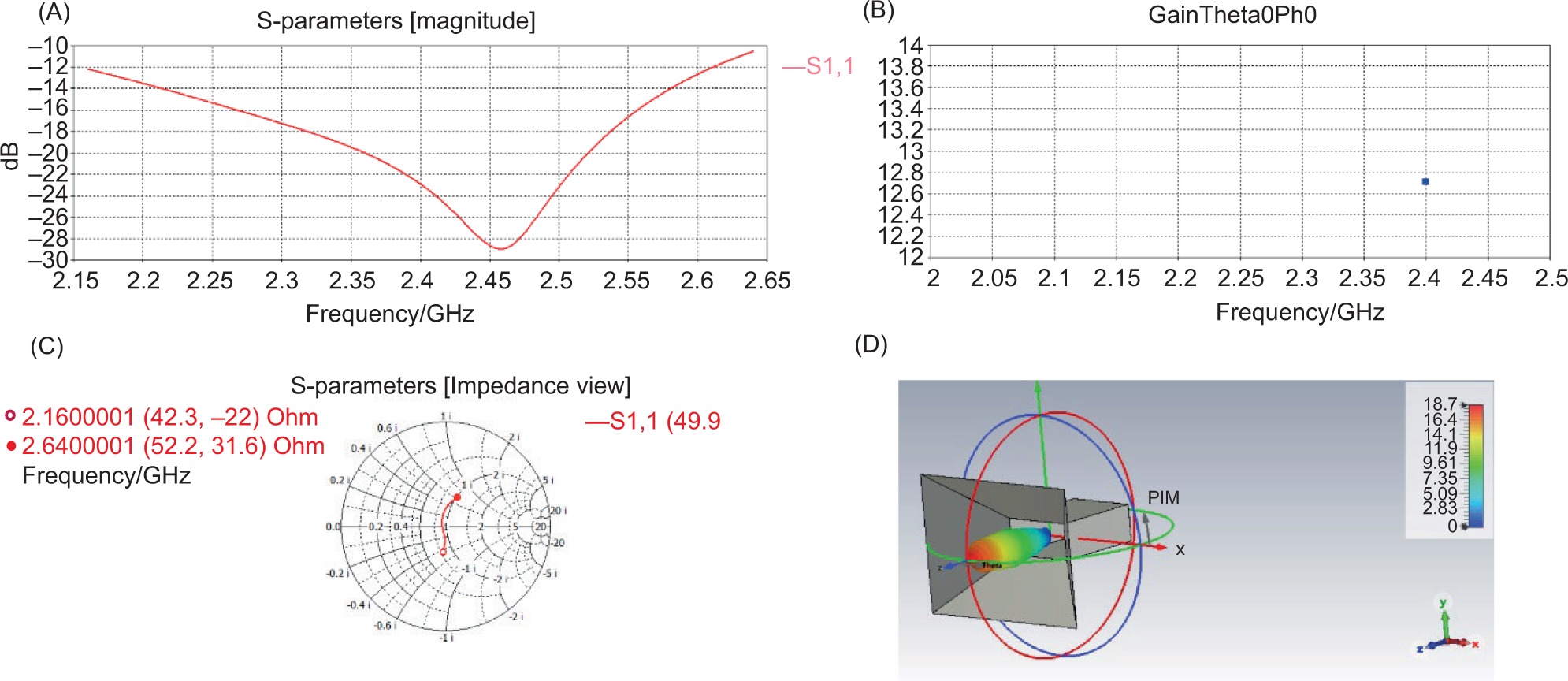
Figure 9C illustrates how the antenna impedance varies with operating frequency. Based on the 3-D radiation pattern plots, we conclude that the antenna is highly directive and has a maximum gain of approximately 12.77 dBi, as shown in Figure 9D.
Initially, the geometry of a pyramidal horn antenna with dimensions of the aperture width Wa =258.9 mm, height aperture wall Ha =187.0 mm, the flare length = 76.79 mm; similarly, dimensions of waveguide width Wg=98.05 mm, waveguide length Hg= 124.91 mm, are modelled in Figure 9D.
The phase errors (H-plane)
The phase errors (E-plane)
The phase error (t) in (H-plane) differs from the phase error (s) in (E-plane). Figure 10 contains a photograph of a pin-feed pyramidal horn antenna. The dimensions of pyramidal flared antennas are 187 mm (width) and 259 mm (height), whereas the thickness of the antenna metal is 0.127 mm.
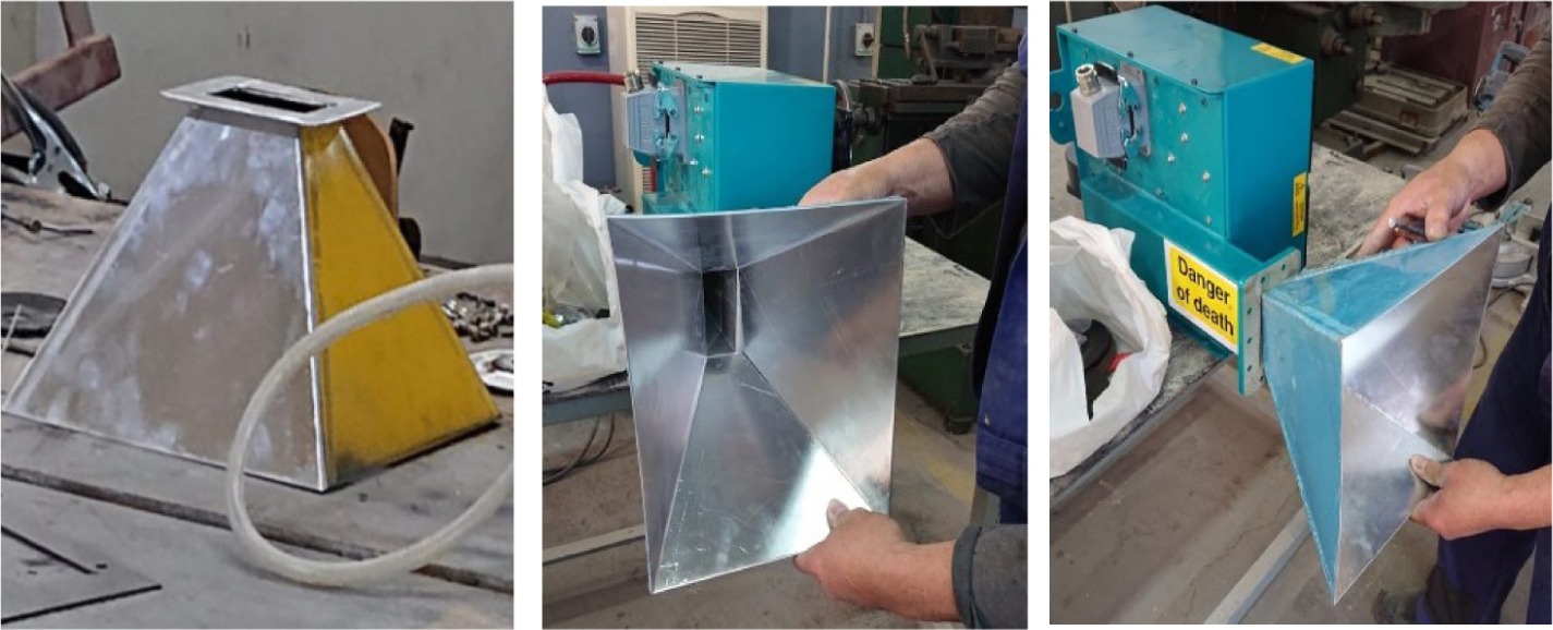
Table 2 has a summary of the distinguishing characteristics of pin-feed pyramidal horn antennas. The antenna’s polarisation is linear and directional, and its impedance is 50Ω.
Power harvester system
Embedded wireless power supplies can provide power to military devices for a 36-hour patrol without any contact and reduce battery weight and size. Microwave energy is converted into DC power by the rectifier circuit. As shown in Figure 11, the wearable harvesting system consists of three elements, and this subsection describes each component in detail.
Twin inset-feed patch antenna
Energy harvesters should be small, lightweight, inexpensive, and easily concealed in clothing. The array patch antenna is the optimal choice for this application due to its flexibility and geometry (Eltresy et al., 2018; Li and Hao, 2017). Generally, broadband antennas can operate across various frequencies, especially when incorporated into protective vests. The radiation strength of a patch antenna feed is dependent on its beamwidth. Accordingly, an RF4 substrate with a dielectric height of 1.6 mm was chosen, which provided the essential design parameters.
Where:
Speed of light C= 3 x 10⁸ m/s
The dielectric constant of the substrate εr = 4.4
The schematic of the microstrip patch antenna showing the optimal parameters for Microstrip Line (MLIN), Microstrip Line Open-Circuited Stub (MLOC), Microstrip Curve (MCURVE), and Microstrip Asymmetric Coupled Line (MACLIN) (Ren et al., 2020). It is necessary to add the MACLIN to the design to create the inset feed line, as shown in Figure 12. According to Equation (18), W1 and W3 are equivalent and determined according to the substrate width (W).
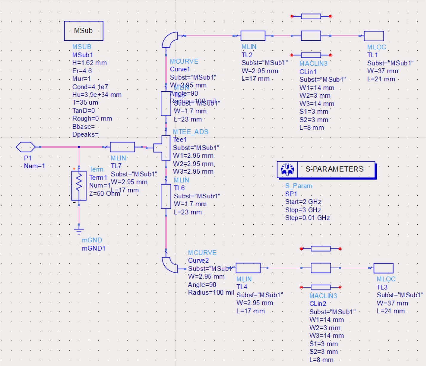
On the other hand, the W2 is equal to the width of the microstrip line feed, s in Equation (18). Moreover, (S1) and (S2) are the gaps of the inset feed, where both were equal to (Wf).
The width of microstrip line feed, (Wf), is computed in Equation (19):
Moreover, the length of the microstrip line feed (Lf) is obtained through Equation (20) below:
Where (λg):
The following Equation is used to calculate the notch width:
In this optimised circuit, with the FR4 dielectric substrate (εr = 4.6, tan δ = 0.02, and h = 1.6mm), fr = 2.4 GHz, the relative bandwidth is more significant than 1%. At 2.444 GHz, the proposed patch antenna has a directivity of 7.431 dBi and a gain of 4.518 dBi, as shown in Figures 13 (a) and 13 (c), respectively. With an operating frequency of 2.431 GHz, we obtained an acceptable return loss, S11= -17.167, dB. At 2.45 GHz, the antenna has a standing wave ratio of 1.056 with a bandwidth of approximately 32 MHz.
Figure 13
Tin inset-feed patch antenna simulation: (A) S11 performance, (B) Current simulation, (C) Antenna Smith chart, (D) Gain and directivity of the proposed antenna
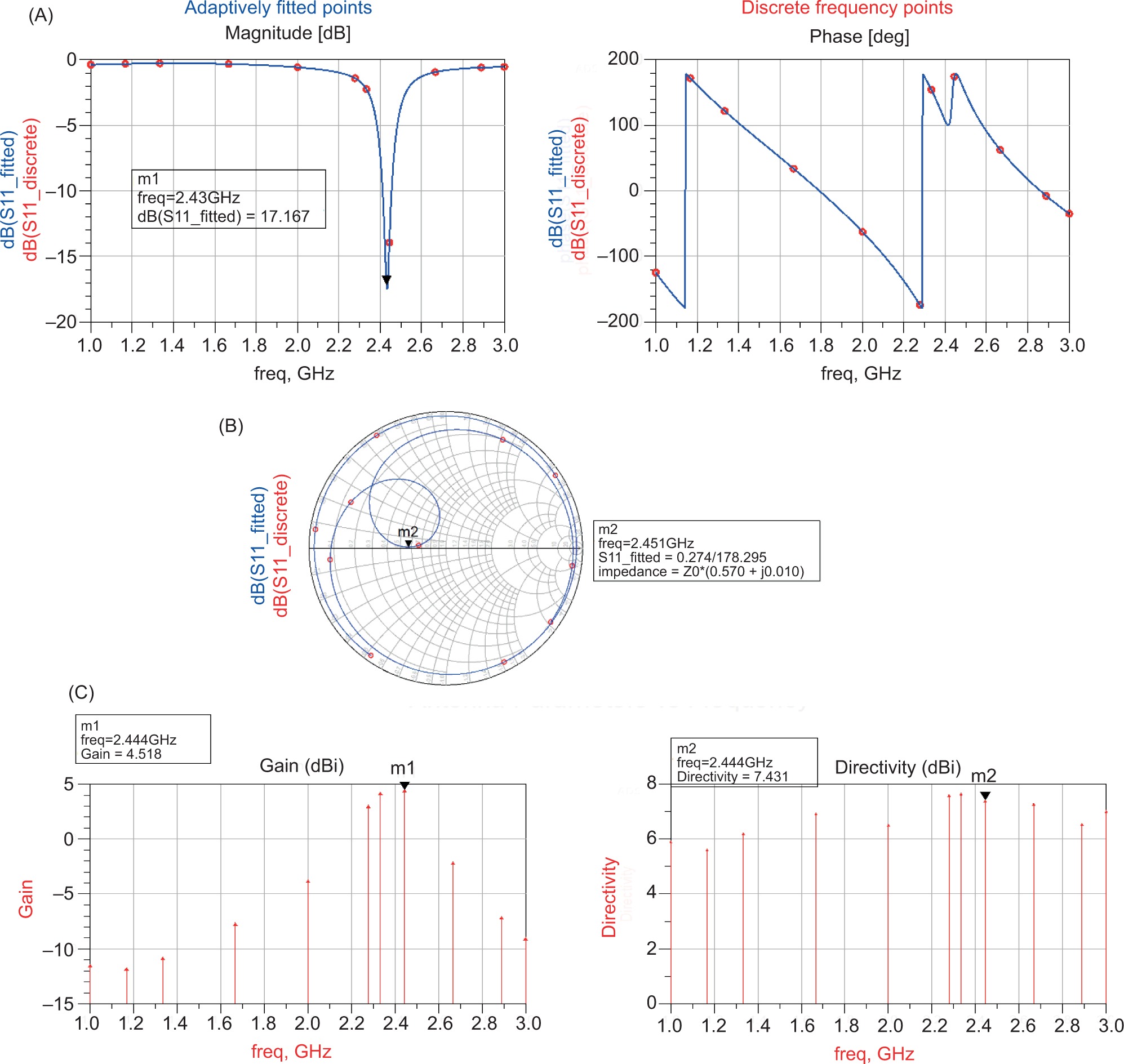
The different widths of the feed lines result in further distribution of current. At 2.448 GHz, we can see that the antenna and the signal source are almost perfectly matched, with no imaginary parts for impedance. This results in the accurate transmission of all signals.
Where:
Z= (Z0 × (0.57 + j0.01)).
This antenna performs acceptably for harvesting RF energy. The next step will be to examine the circuit design for rectifier harvesters.
Rectifier Investigation
This section describes the fabrication of RF rectifiers, starting with selecting components according to the desired output voltage and output current and analysing the performance of the RF rectifier harvesting circuit based on high-frequency diode components (Akter et al., 2014; Ali et al., 2016; Chaari and Al-maadeed, 2020; Matsunaga et al., 2015; Pinto et al., 2021). The output voltage (Vout) achieved is given by this variation in (RL) value, as present in Equation (23):
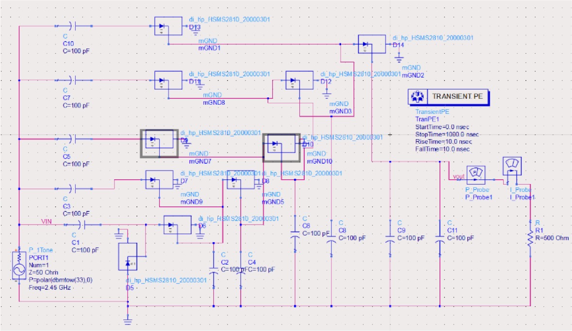
As shown in Figure 14, a Schottky diode named HSMS2810 is used as part of the RF energy harvesting circuit. In this experiment, the voltage gain decreased as the number of steps increased, whereas a higher voltage is obtained by increasing the number of steps.
Figure 14
Circuit design for RF harvesting utilising a five-stage voltage multiplier with the diode HSMS-2810 (Agilent ADS).
As shown in Figure 15, the DC output voltages obtained from the simulation of a five-stage voltage multiplier are 7.031V when using HSMS2700 diodes. We simulate a five-stage voltage multiplier using different Schottky diodes until we reach the high output voltage (HSMS2800, HSMS2850, HSMS2860, HSMS2810, HSMS810, HSMS2700, HSMS270B). According to Table 3, the HSMS-281X family has a high output voltage due to low flicker noise.
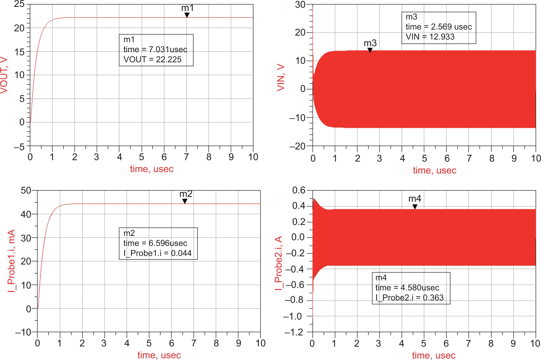
Table 3
Schottky diode HSMS-2800, HSMS-2850, HSMS-2860, HSMS-2810, HSMS8101, HSMS2700, and HSMS-270B efficiency comparison.
It has a low series resistance, low forward voltage at current levels, and good RF characteristics, making it an excellent choice for RF scavenging. The HSMS-285x detector diodes, as shown in Table 3, are zero-bias detectors designed for applications that involve small signals below 1.45 GHz. Schottky diodes HSMS-2850, despite their apparent high series resistance, provide low power levels in all the above RF rectifier topologies.
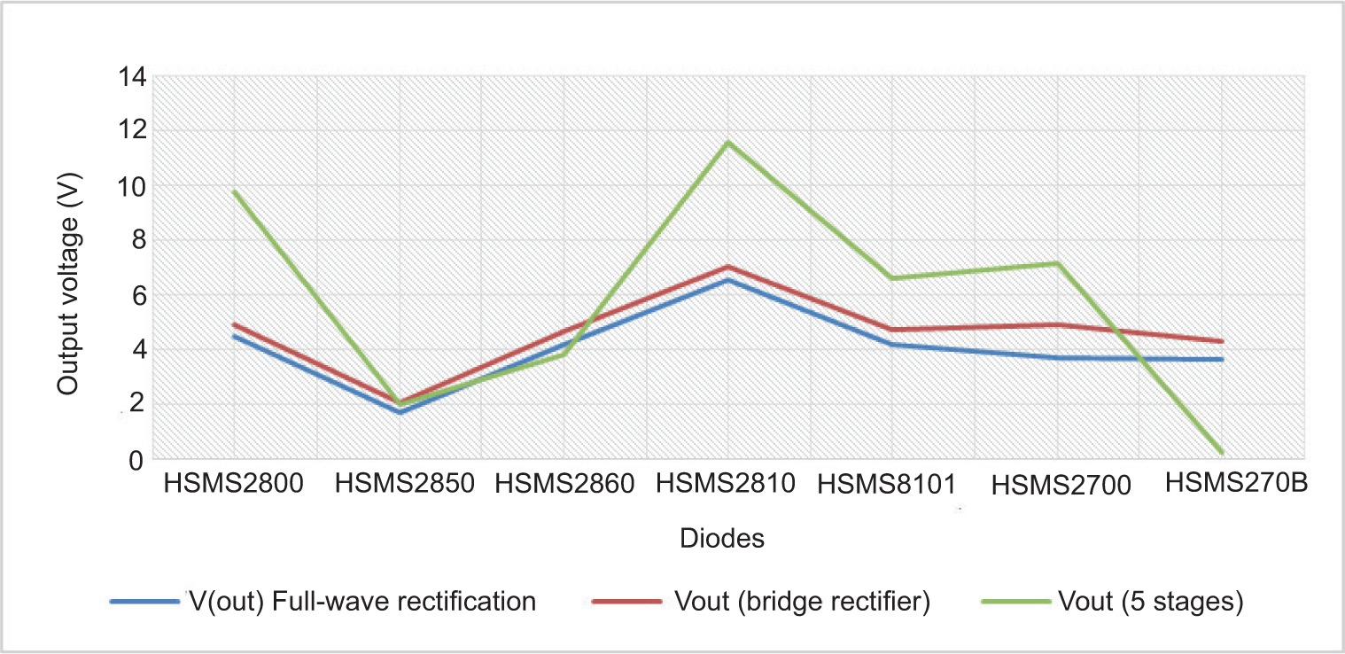
HSMS 8101 is approximately 3.1 times more efficient than HSMS 2850, as shown in Figure 16. In this test, HSMS 2810 provides high output voltage.
Prototype result and discussion
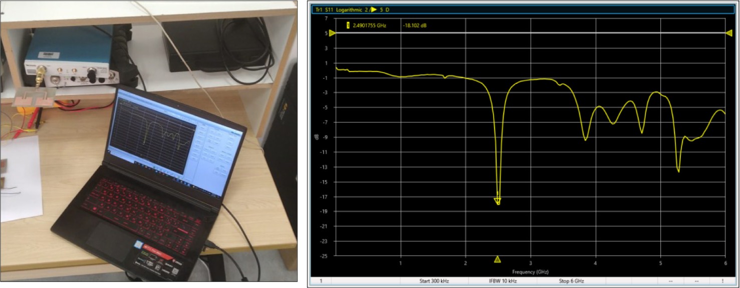
The portable microwave radiation station features a power output range of 100W to 2kW and operates at a frequency of 2.45GHz. Wireless energy calculators use equations to estimate the amount of microwave energy present at the receiver and the level of RF power converted to DC outputs, assuming a direct line of sight between the patch antenna and the horn antenna. We entered the gain values of the (Tx) and (Rx) antennas into the wireless power calculator. To measure the S11 of the fabricated antenna, we used a vector network analyser (VNA) TTR506A. As shown in Figure 17, the estimated S11 value is -18.102 dBi, while the theoretical simulation value is -17.167 dBi. Accordingly, this antenna matches much better at 2.45 GHz, with a smaller reflection. A receiver antenna’s maximum Gain is 4.510 dB. (TX) antenna prototypes have been constructed and measured using the Vector Network Analyser to determine the S11. S11 was estimated to be -26.13 dBi instead of -28.16 dBi as predicted. The receiver antenna can achieve a gain of 12.510 dB. Using a patch antenna and HSMS-2810, the rectenna generates a maximum DC voltage of 11.7 V, with an efficiency of 18.75 percent, at an RF power of 20 W.
The line of sight (LOS) between the antennas is one metre to five metres for outdoor testing.
According to Table 4, the strength of the RF power varies with the distance between the microwave power station Pin = 100 W and the receiver circuit. It appears that the harvested power varies significantly with distance.
Table 4
Energy harvesting range/distance
| RF Power transmitting (Pr) | There is a gap between the RF transmitter and the observation point | Harvested energy |
|---|---|---|
| 100 W | 1 metre | 26.22 W |
| 2 metres | 19.56 W | |
| 3 metres | 14.56 W | |
| 4 metres | 14.62 W | |
| 5 metres | 10.03 W |
As a transmitter source, we fixed the RF power at 100 Watts. The rectifying circuit is connected to the twin inset-feed patch antenna using the SMS connector. Figure 18 shows how the bulbs are powered wirelessly.
Conclusion and perspectives
Using an RF energy harvesting device, this project investigated the possibility of generating electricity from the ISM-band to charge many devices on the battlefield. This device can integrate into a protective vest in the future. During a real test, the receiver patch antenna had a reflection coefficient of -32.34 dB and a gain of 15.11 dB. The harvester antenna meets all the specifications required for this application. It produces a high output DC voltage and provides excellent conversion to electricity. At five metres, we achieved 13 watts. In this study, we discovered that wireless power technology could reduce the weight a soldier carries and that soldiers could wirelessly charge all their electronic devices. The effects of this technology on the body of a soldier are not of concern to us, and it is extremely critical to keep it alive and in contact with the command centre. We will change the topology of the rectifier circuit in the next step and check the harvesting circuit’s efficiency.